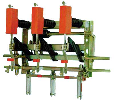
The load disconnectors are used as loading devices in medium
voltage, indoor operating environment, in normal operating conditions (class
"minus 15", indoor design).
The design of H27 load disconnectors complies
with the requirements of IEC 694, IEC 129 and IEC 265 standards.
The H27
load disconnectors are supplied with the following phase pitch design: 275 mm,
225 mm and 170 mm.
All parts and frames made of steel are galvanized and
chromate coated.
The drive shafts are seated in bronze bearings and this is
why the material as such can not be subjected to corrosion.
All parts of
the current carrying path are made of drawn electrolytical copper.
The control of load disconnectors occurs through the
following:
- SHA hand operated drives (for load disconnectors mounted on the front
wall), with the possibility of both right-side and left-side mounting to the
load disconnector
- adaptor for "D" type drive, with an extension part (in case of
necessity, for load disconnectors mounted to the side wall)
- UM50 motor operated drives (mounted directly to the operating shaft of
load disconnector, usually installed on the left side)
- UM10, UM20 or UM30 motor operated drives (control and manipulation from
the front side of cubicle)
In case when the load disconnector is equipped with earthing
switch there is to be additional drive mechanism to provide for the control of
the earthing switch.
Under normal operating conditions it is not
necessary for the load disconnectors to undergo a preventive maintenance
during the period of ten years.
- a reliable and safe arc extinguishing
- increased safety of the operating personnel due to the use of earthing
loades with an increased short-circuit withstand capability
- load disconnectors of a compact design, necessitating only a very
limited area in the respective loadgear frame or cubicle
- current disconnecting path which can visually be inspected
- easy operation
- high number of loading cycles
- very limited maintenance requirements
- no necessity to use burn-up contacts or contacts with delayed
operation
H 27 EK |
for wall mounting, quick-make and quick-break operation |
H 27 EA |
for wall-mounting, quick-make and quick-break operation, trip-free
|
H 27 SEA |
for wall mounting, quick-make and quick-break
operation, trip-free
fuse holders mounted below for high-voltage
high-breaking-capacity (HV HBC) fuses with striker release 1)
. When a fuse is blown the disconnecting mechanism disconnect all
the three poles of the load disconnector. |
H 27 SuT |
for side mounting, quick-make and quick-break operation,
trip-free
fuse holders mounted below for HV HBC fuses with striker
release
When a fuse is blown the disconnecting mechanism disconnect
all the three poles of the load disconnector. The contact counterparts
are mounted on supports on a special console. The fuses can be removed
from the side. |
H 27 F-EK |
for front-panel mounting, quick-make and quick-break operation |
H 27 F-EA |
for front-panel mounting, quick-make and quick-break operation,
trip-free |
H 27 F-SuT |
for front-panel mounting, quick-make and quick-break operation,
trip-free
integrated fuse tripping mechanism for HV HBC fuses
with striker release. Insulators with mounted HV
HBC fuse holders on two special consoles. |
1) Starting actuating force of the rod is 80
N.
All models with the exception of H 27 SuT and H 27 F-SuT are
available with or without integrated earthing switch with short-circuit making
capability (UESV). In the case of load disconnector H 27 SuT is the earthing
switch with short-circuit making capability (UESV) mounted on the special
consol (this can be fitted subsequently).
The H27 F-SuT load disconnectors
can be provided with a special earthing load having the short-circuit
withstand capability (UESV) and with a built-in drive disc used for the
loading via operating lever.
Supplementary material to the disconnectors
Working release |
110V and 220V AC, 24V, 60V, 110V and 220V DC
The H22
EA and H22SEA load disconnectors can be equipped with a working
release.
Simultaneously, the function of release can be blocked with
an additional switch. |
Additional switch |
in order to indicate the switching position the
disconnectors with built-in earthing switches can be equipped with
additional switches
The basic setup of switches can be modified
without the necessity to disassemble the disconnector, by using special
tools (such as when changing the contacts from making to breaking, or
changeover contact etc.). |
Motor operated drive |
see operated drives catalogue |
The customer has to state in his order the respective load
disconnector design, with regard especially to the installation position
(horizontal or for ceiling assembly).
Energy storage mechanism
One of the robust, low-maintenance energy storage mechanism
of type EK or EA is mounted on the base frame, on which the three switch poles
are installed. Many hundred thousands of these devices have already been used
successfully in the H 22 load disconnectors.
The EK energy storage
mechanism operates with only a single torsion spring gor quick-make and
quick-break operation without trip-free release. The torsion spring is
tensioned for switching ON or OFF. After tensioning, the spring energy is
released for the particular switching operation (ON or OFF).
The EA
energy storage mechanism operates with two torsion springs for trip-free
quick-make and quick-break operation.
Both torsion springs are tensioned
when the switch is closed.
The ON switch spring is tripped after tensioning
and releases its energy for switching ON, while the OFF witch spring remains
tensioned until it is released by the tripping device, HV HBC fuses with
striker release, or manually for switching OFF.
With non-manual release the
operating shaft remains in the ON position and must be moved to the neutral
position OFF manually for reclosing.
Wall-mounting devices can be actuated
via a linkage system operated by a detachable lever or by any of the actuators
according to requirements and situation.
Laterally mounted switches can be
operated directly by fixing a sleeve for D-drives with internal twelve-sided
polygon 24 on the operating shaft and using the detachable lever with
hexagonal attachment.
Front-panel mounted devices can be operated by means
of a detachable lever with a driving pulley integrated in the switch.
Arc extinction
When a breaking process occurs to the load disconnector the
loading knife (5) with arcing tip (6) moves from its position in the
front-side contact (2). The electric arc is then interrupted in the arcing
chamber (4). The chamber is of closed design, consisting of four parts,
encompassing the pressure and expansion room. The pressure room there are two
extinguishing elements (3) that are moved into the path of arc by using the
side pressure of spring. In the ranges of small currents the arc extinguishing
process is based on the deionization effect of the arc which is cooled down on
the walls of arc extinguishing plates. High current arc is extinguished by gas
flow which is generated by the arc in the chamber pressure room and which
flows into the expansion room.
As you can see, in all the cases there is a
combination of a series of arc extinguishing principles that provide for a
safe current breaking over the whole current range of the load disconnector.
The arcing chambers as such are completely maintenance free.
 |
<-ON |
OFF-> |
 |
|
1 upper connecting contact
2 contact jaw
3
extinguishing plates
4 arcing chamber
5 switch blade
6 arcing
tip
7 roller guide contact
8 guide lug
9 lower connecting
contact |
Maintenance-free load disconnector operations as a function of
the breaking current at cos j ³ 0.7.
|